Agen Resmi Teledyne LeCroy Indonesia
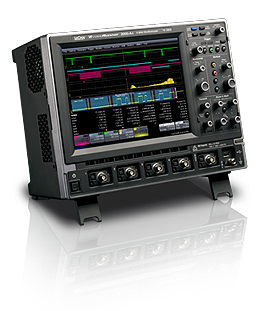
VBA Xi-A Vehicle Bus Analyzers
The Vehicle Bus Analyzer is the first conventional oscilloscope to dispay both the full range of CAN protocol stack information-symbolic, hex, and electrical signal--and to view additional in-circuit electrical signals (sensors and actuators, voltage levels, transients, etc.) that influence the CAN bus.Explore Vehicle Bus Analyzer (Xi-A)

VBA204Xi-A (2 GHz Bandwidth, 4 Input Channels, 5 GS/s Max Sample Rate)
Limited Availability
Limited Availability
Quick Specs
VBA104Xi-A (1 GHz Bandwidth, 4 Input Channels, 5 GS/s Max Sample Rate)
Quick Specs
VBA64Xi-A (600 MHz Bandwidth, 4 Input Channels, 5 GS/s Max Sample Rate)
Quick Specs
VBA44Xi-A (400 MHz Bandwidth, 4 Input Channels, 5 GS/s Max Sample Rate)
Check up to three models.
Quick Specs
VBA204Xi-A (2 GHz Bandwidth, 4 Input Channels, 5 GS/s Max Sample Rate)
Limited Availability
Limited Availability
Quick Specs
VBA104Xi-A (1 GHz Bandwidth, 4 Input Channels, 5 GS/s Max Sample Rate)
Quick Specs
VBA64Xi-A (600 MHz Bandwidth, 4 Input Channels, 5 GS/s Max Sample Rate)
Check up to three models.
The Vehicle Bus Analyzer Speaks Your Language
The Vehicle Bus Analyzer decodes CAN serial data into Symbolic
(application layer ) text directly on the oscilloscope display. For the
first time, an engineer has both the full range of CAN protocol stack
information—symbolic, hex, and electrical signal—and the ability to view
additional in-circuit electrical signals (sensors and actuators,
voltage levels, transients, etc.) that influence the CAN bus. In
addition, up to four different CAN buses can be decoded at one
time.Standard and specialized oscilloscope tools can be used to validate
and debug designs.
Features
- CAN symbolic (Application Layer) decode of up to 4 CAN buses
- CAN triggering with setup in symbolic format
- CAN digital date extraction with symbolic format setup and plot data as an analog signal
- CAN automated timing measurements
- Compatible with CAN DBC database format
- Includes CANbus TDM, FlexRay TDP, and LINbus TD solutions
- FlexRay, Trigger, Decode, and Physical Layer testing (version 2.1)
- LIN Trigger and Decode supported for 1.3, 2.x, J2602 versions
- FlexRay eye diagram mask testing with error location
- FlexRay physical layer measurement para meters for propagation delay, asymmetric delay, truncation and jitter
- Capture thousands (seconds) of CAN, FlexRay and LINbus messages with up to 25 Mpts of memory
Eliminate the Barriers to Fast Debug
Direct symbolic decoding and triggering allows fast and intuitive
understanding of events.Simply load your existing DBC database file into
the oscilloscope (no re-entry of data is required); capture CAN message
traffic; and all electrical (signal), protocol (hex), and symbolic
(application) layer information is quickly displayed on the oscilloscope
screen. Use standard oscilloscope and specialized Vehicle Bus Analyzer
tools to find rare events, automatically measure and statistically
analyze event timing, and graph/plot information, including extracted
CAN message data.
The Single Tool Enhances Productivity
The VBA concentrates all your information in one place. Timing
measurements across gateways are now possible. Under standing is fast,
intuitive, and in a familiar format. Complete, time-correlated
understanding of all ECU or circuit behaviors is simple. Time-consuming
workarounds are a thing of the past.
Unique Measurement Tools
The VBA can make many measurements not possible with other
instruments. Aside from timing measurements, the VBA can also extract
CAN digital data from a CAN message stream, graphically plot that data
as an analog signal on the oscilloscope display, and compare it to other
electrical signals. Here, information on the steering angle and
steering angle rate of change is extracted from the CAN message
acquisition, rescaled to decimal values, and plotted as a
time-correlated "Track" on the VBA display.
Vehicle Bus Analyzer Software Capabilities
- Symbolic (application layer) decode of up to 4 separate CAN bus
- Symbolic CAN trigger setup
- Hexadecimal decode and trigger setup for CAN, FlexRay and LINbus.
- Binary trigger setup
- Automated timing measurements, including capability to measure timing across gateways:
- CAN message to Analog signal
- Analog signal to CAN message
- CAN message to CAN message
- Bus Load % measurements (up to 2 billion events)
- CAN digital data extraction and display in analog form in scaled decimal values
- CAN message bit rate calculation
- Statistical calculations of many measurements
- Histogram (graphical) display of statistical data, including timing measurements
- Trend and Track plots of extracted CAN data
- Persistence trace, mean, and sigma functionality
- Complete set of Jitter and Timing (@level) parameters
- Supports for 2.5, 5, and 10 Mb/s FlexRay signals
- Physical layer measurement parameters for propagation delay, asymmetric delay, truncation and jitter for FlexRay.


